# Open-hardware for electrostatic discharge testing (O-ESD)
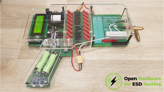
O-ESD is open-hardware project for (pre-compliance) [ESD immunity testing](https://en.wikipedia.org/wiki/IEC_61000-4-2) in accordance with [IEC/EN 61000‑4‑2](https://webstore.iec.ch/en/publication/68954) standard. It is a stand-alone battery-powered portable device that can produce low-energy voltage pulses in the range from –15 kV to 15 kV. All electronic devices must be immune to a certain level of ESD, as ESD happens everyday between humans and electronic devices.
O-ESD is released under [CERN Open Hardware License Version 2 – Strongly Reciprocal](https://o-esd.etf.bg.ac.rs/IMG/cern_ohl_s_v2.txt).
The current release is [version 1.0](https://o-esd.etf.bg.ac.rs/forgejo/dragan.olcan/O-ESD/src/branch/main/v1.0).
Electrostatic discharge can irreparably damage electronic devices. Use O-ESD with caution!
## Features
* Contact discharge mode and air discharge mode.
* Both positive and negative polarity of the output voltages for all levels.
* Open-circuit output voltage at terminals from 1 kV to 12 kV for the contact discharge.
* Open-circuit output voltage at terminals from 1 kV to 15 kV for the air discharge.
* Single-discharge mode and user-defined pulse repetition.
* User-defined hold time for output voltage for air discharge.
* Equivalent capacitance seen from the output terminals 100 pF.
* Equivalent resistance seen from the output terminals 330 Ω.
* ESD pulse in accordance with IEC/EN 61000-4-2.
* ESD pulse energy up to 17 mJ.
* Powered by two 18650 3.7 V Li-Ion rechargeable batteries.
* 15 hours of continuous operation (using fully charged 3200 mAh batteries).
## Quick-start guide
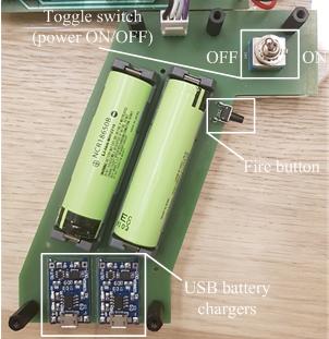
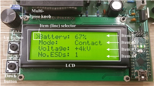
The O-ESD is powered up (or down) using the toggle switch located on the grip. The O-ESD user interface consists of: toggle switch (ON/OFF), fire button, USB battery chargers (optional), LCD, down button, up button, multi-purpose knob located on the left side of the LCD.
Once the O-ESD is powered-up the splash screen should appear for 1 s at the LCD. Afterwards, the main screen of the O-ESD shows up. LCD has four 20-character lines. Each line stands for one item. Items (i.e., lines) are selected by moving the selector “ > ” using up/down buttons.
If an item has a numeric value selectable by the user, the numeric value can be changed by rotating the knob. Some items have multiple choices (selections) or submenus (sub-items) available and those are accessible by pressing the knob.
There are two modes of operation
(a) contact discharge
(b) air discharge.
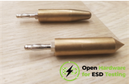
The default mode is the contact discharge. The sharp conductive tip (electrode) is used for contact discharge and should be placed in the red socket at O-ESD output. For air discharge the rounded conductive tip (electrode) is used and it should be placed in the black socket. O-ESD is intended for use with only one conductive tip (electrode) inserted at a time and with the appropriate mode of operation selected.
Screen (menu) has four items.
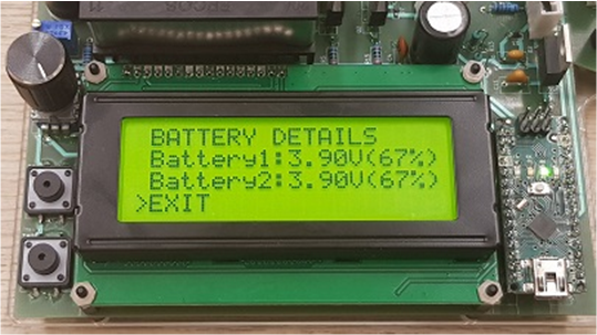
(1) The first (top) item on LCD is the battery status. It displays the minimum of relative voltages of the two batteries. If the voltage of a battery drops below 3.5 V, the battery status displays that recharge is needed. Note that O-ESD will work even with very low battery voltage that may irreparably damage the batteries. Battery status has a submenu that presents extended information about each battery.
(2) The second item is the operation mode. It can be either contact or air as selected by the used.
(3) The third item is the ESD voltage level. The ESD voltage can be in the range from –12 kV to 12 kV in the case of contact discharge, or in the range from –15 kV to 15 kV in the case of air discharge. Note that the sign of the charge (polarity) is defined by the position of the cascade, i.e., it should be placed in the correct position in order that given polarity can be produced at the output.
(4) The forth item (at the bottom of LCD) is
(4a) the total number of pulses in the case of the contact discharge or
(4b) the hold time in seconds for air discharge (i.e., the time window in which the rounded tip is at the predefined voltage until the air discharge happens).
Once the user has selected the mode of operation, ESD voltage level and number of pulses (or hold time), the discharge is initiated by pressing the fire button on the grip. During all the specified discharge(s) cycles, the information about discharge is displayed on LCD and the O-ESD main screen is inaccessible.
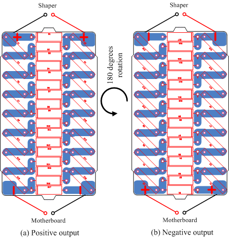
The sign (polarity) of the output is determined by the cascade connections to the shaper and the motherboard. The opposite sign is achieved by rotating the cascade for 180 degrees, i.e., the sign of the output is the one printed on the cascade end connected to the shaper. Before disconnecting and rotating the cascade, wait for 10 seconds after the last discharge so that the cascade discharges fully.
When not in use, O-ESD should be turned off using the toggle switch on the grip.
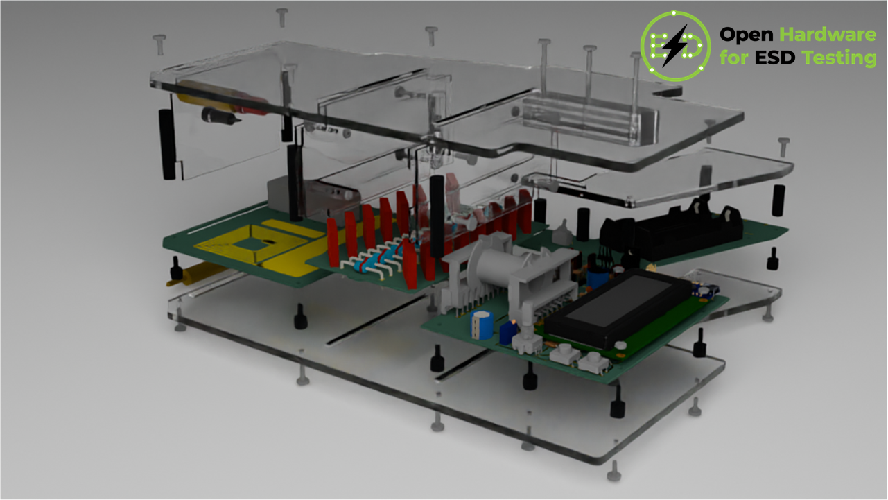
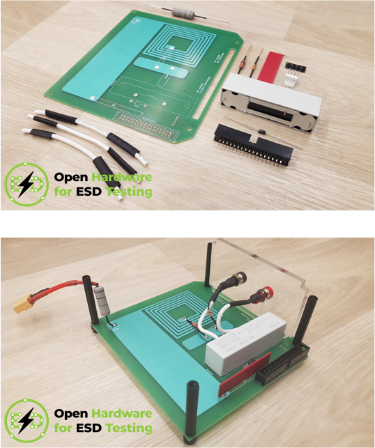
## Assembly
O-ESD consists of six parts:
(1) Mechanical support.
(2) Grip.
(3) Cascade.
(4) Shaper.
(5) Claws and strap.
(6) Motherboard.
Bill of materials (BOM) is available at link.
Design files are available at link.
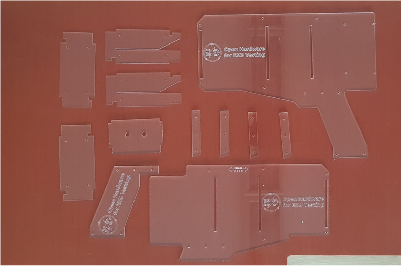
### Mechanical support
Mechanical support consists of laser-cut acrylic glass, bolts, nuts and spacers, all made from nonconductive materials.
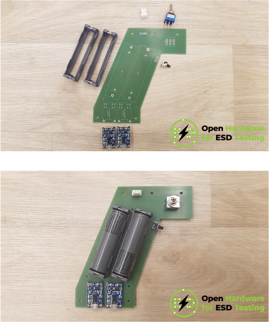
### Grip
The grip is a separate PCB connected to the motherboard with 4-wire cable. The main purposes of the grip are: to house batteries, to provide physical grip of O-ESD, to house toggle switch, fire button and optionally battery chargers.
### Cascade
The cascade is a separate PCB connected to the motherboard and the cascade with two 2-wire cables with XT60 connectors at each end. The main purpose of the cascade is to provide high-voltage DC for the shaper.
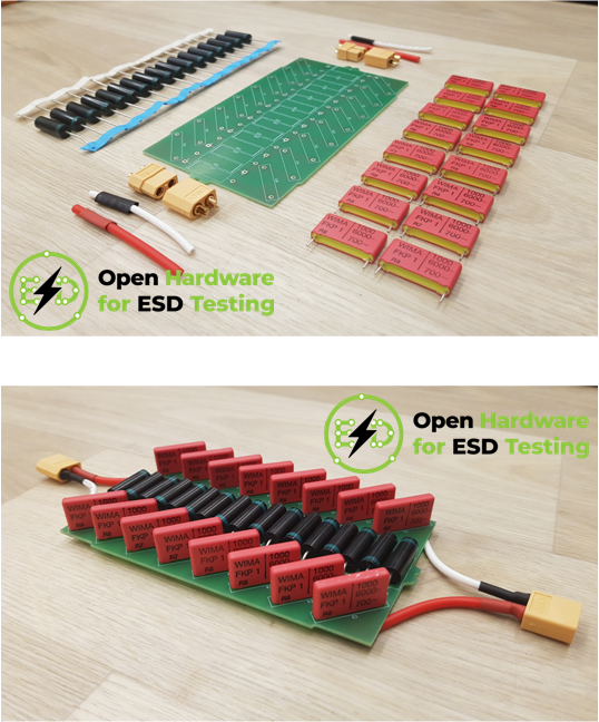
In order to prevent losses from the corona effect, assembled cascade can be coated with corona-protective insulating material (e.g. Plastik70 from Kontakt Chemie or similar).
### Shaper
The shaper is a separate PCB connected to the mother board (with 4-wire cable) and the cascade (with 2-wire cable with XT60 connector). The main purpose of the shaper is to generate pulse according to IEC/EN 61000‑4‑2.
In order to prevent losses from the corona effect, all conductive surfaces on the assembled shaper (except the flat-cable connector) can be coated with corona-protective insulating material.
Sharp and round tips according to the standard including 4mm connectors should be custom made.
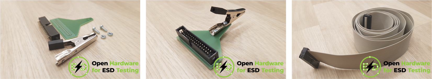
### Claws and strap
The strap is 2 m 34-wire flat cable connected to the cascade with 34-bin boxer connector. The other end of the strap is connected via 34-pin boxer connector to PCB with claws for GND contact. The main purpose of the claws is to provide easy way of connecting the ground of O-ESD, while the strap connects the O-ESD and the claws.
### Motherboard
Motherboard is a separate PCB connected to the grip (with 4-wire cable), to the cascade (with 2-wire cable with XT60 connector) and to the shaper (with 4-wire cable). The main purpose of the motherboard is to orchestrate the functioning of O-ESD and to provide the user interface.
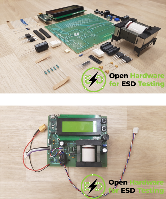
All components of the motherboard except step-up transformer are available on the market. The step-up transformer must be assembled per specifications.
The transformer has the following roles
(a) to accumulate energy while the switching transistor is in the on state and release that energy to the high-voltage cascade when the switching transistor goes to the off state
(b) to provide step-up voltage transformation from the low-voltage input to the high-voltage cascade and
(c) to provide galvanic insulation between the low-voltage input and the high-voltage cascade.
Windings:
(1) The primary and the secondary are to be wound on the coil former.
(2) The total number of turns for the primary winding is 4.
(3) The total number of turns for the secondary winding is 1860, i.e., about 155 per layer, 12 layer in total.
(4) The sense (direction) of the windings should be the same.
(5) The high voltage (secondary) winding shall be wound first. The low voltage (primary) winding shall be wound on top of it.

Winding can be performed using a winding machine or produced manually, with care. The number of turns per layer of the secondary winding can be counted or can be estimated from the inside length of the coil former and the wire AWG.
Regardless of the winding method, the beginning of the high voltage coil, which comes closest to the ferrite core, shall be inserted in heat shrink tubing and the tubing shall be heated to its final dimensions. The tubing is used to improve the insulation between the wire at the beginning of the coil and other wire layers.
Once a winding layer is completed, it shall be fully covered by layers of insulation paper. The total thickness of the insulating layer must be at least 0.2 mm. The first role of this insulation is to reduce the parasitic capacitances between adjacent wire layers. The second role is to increase the breakdown voltage between adjacent wire layers.
The completed secondary winding shall be covered by layers of insulation paper either fully or only in the area where the primary winding is going to be placed. The main role of this insulation is to increase the breakdown voltage between the two windings.
Once both windings are completed, the insulation from all wire ends shall be removed. Solder the terminals of the primary and secondary windings according to raster view. The beginning of the secondary winding (which is covered by the heat shrink tubing) shall be soldered to the pin denoted by the red circle in raster view.
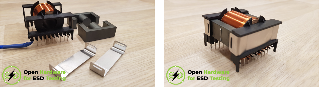
Insert the two halves of the ferrite core into the coil former shown in assembly of the step-up transformer. The cross sections of the core in the areas denoted by green ellipses should have gaps of 0.25 mm to 0.3 mm. Cut three pieces of the standard printing paper (80 GSM) per gap, and stack pieces to form the gap. It is not necessary to place the paper in the central column of the core.
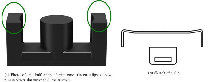
Secure the transformer by two clips. One clip is shown in Sketch of a clip. The location of the clips can be seen in assembled step-up transformer.
## Use-case scenarios for testing and demonstration
Five use-case scenarios for electrostatic-discharge testing and demonstration of ESD effects are [presented](https://o-esd.etf.bg.ac.rs/forgejo/dragan.olcan/O-ESD/src/branch/main/Demos#).
Assembly instructions and explanations, including videos, can be found on [O-ESD GIT](https://o-esd.etf.bg.ac.rs/forgejo/dragan.olcan/O-ESD/src/branch/main/Demos/Readme_demos.pdf).